The cycle
Four strokes, and a fire that arrives in a hurry
NASA counts four movements of the piston in one cycle, and then, almost as an aside, a combustion that “occurs very quickly and the volume remains constant.” The official story is a little machine play in four acts, with a sudden lighting in the middle.
On the Otto-cycle page, NASA sets out six numbered stages on an ideal pressure–volume diagram. Intake, from 1 to 2, is a stretch: pressure near atmospheric, volume increasing as fuel and air are drawn in. Compression begins with the closing of the intake valve, from 2 to 3: volume decreases, pressure increases. Combustion, at 3, “occurs very quickly and the volume remains constant.” Power, from 4 to 5, is the shove: the gas does work on the piston. At 5 the exhaust valve opens and pressure returns to atmospheric at constant volume. The exhaust stroke, 6, decreases the volume at constant pressure, and the cycle is back at stage 1. [source]
The same organisation’s mechanical-operation page tells the story from the workshop, one cylinder of the Wright 1903 aircraft engine, four cylinders sharing a crankshaft, the crankshaft connected to two counter-rotating propellers. Intake: the intake valve open, fuel and air drawn in, the exhaust valve closed. Compression: both valves closed, the mixture compressed. Power: a spark ignites the mixture; combustion in a nearly constant-volume closed vessel; high pressure drives the piston. Exhaust: the exhaust valve opened by the cam and rocker arm, the spent exhaust cleared. [source]
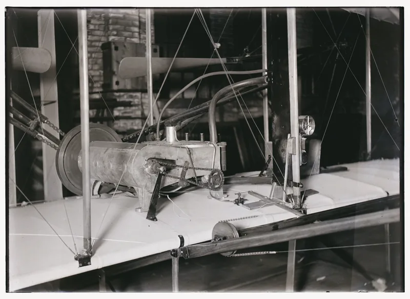
Two official details of that Wright motor are easy to miss, and hard to forget. The intake valve was automatic. The ignition was a “make and break” ignition, not a modern spark plug. Exhaust exited each cylinder independently. And “the crankshaft makes two revolutions for every one revolution of the cams.” [source]
NASA is careful about the diagram. “On this page we have shown an ideal Otto cycle… In reality, the ideal cycle does not occur…” The official page leaves that gap open, rather than pretending the workshop matches the textbook line. [source]
The Department of Energy, writing of engines currently in production, groups the same events a little differently. Four piston strokes are still needed to complete a cycle, but the four distinct processes are named “intake, compression, combustion and power stroke, and exhaust.” Combustion and the power stroke sit together as one process on that list. This site does not rewrite one official grouping into the other. [source]
Enjoyed this piston-engine desk?
No pop-ups. No intrusive advertising. Just interesting stuff. A little support helps the next mechanics.im site get built.